Setting the standard
Aligning the MEMS Digital In-place Inclinometers with the International Organization for Standardization guidelines
Vertical in-place inclinometers (IPIs) are used to measure relative horizontal displacements in a wide variety of geotechnical monitoring applications. Clients rely on IPIs to produce reliable and trustworthy data, from large-scale landslide investigations and monitoring slope stability to the monitoring of retaining structure or pile performance where every millimetre counts. Some monitoring specifications in urban environments can be as stringent as requiring no more than 6mm (1/4”) to 12 mm (1/2”) movement of retaining walls of urban excavations over the full depth of the excavation. In other words, IPIs are used in situations to measure a high amount of displacement, like a landslide, or in situations where it is important to prove little to no displacement is occurring, like in urban excavations.
RST Instruments wants its clients to monitor with confidence. So, conforming to a standard for quality and reporting the instruments’ specifications is essential.
Specification standards
The International Organization for Standardization (ISO) is one of the most recognized non-government organizations that develops and shares management standards that cover nearly all aspects of technology and manufacturing.
Since its launch in 2020, RST Instruments’ latest generation IPI meets and exceeds the requirements set out in the ISO for sensor performance. And now, RST Instruments has aligned how it reports its MEMS Digital In-Place Inclinometer System specifications to conform with the guidelines set in the ISO 18674-3 standard.
Why the change? First, let’s look at some context.
Different specifications for different inclinometer systems
Up until the change, RST Instruments—not to mention other instrumentation manufacturers—reported the specification of repeatability as +/- 2 mm for 30 metres for in-place inclinometers as a prevalent specification.
Pierre Choquet, VP of Business Development with RST Instruments, explains that this specification comes from manual probe-style inclinometers.
“That [specification] means if we asked an operator to repeat the survey two times in a 30 meter long borehole, one time after the other the probe survey delivers a reading within +/- 2 mm ,” he says.
With IPI installations, however, repeatability as a specification is sort of a contradiction in terms, as typical IPI installations are for either long-term or permanent monitoring applications. Another consideration is that all IPIs experience a period of settling, generally not longer than 1-2 days, after the installation as their mechanical components adjust and rest.
When ISO published the 18674-3:2017 specifications on Geotechnical monitoring by field instrumentation, Part 3: Measurement of displacements across a line: Inclinometers, RST Instruments was already looking to develop the next generation of its in-place inclinometer. Pierre notes that it made sense to ensure the new IPI aligned with the language set out in the standard.
What sensor specifications changed?
Sensor accuracy, sensor precision, sensor 24-hour stability, and system precision have replaced the previous specifications.
MEMS DIGITAL IN-PLACE INCLINOMETER SENSOR SPECIFICATIONS
| RST Instruments Specification | ISO 18674-3 Requirement | |
| Range | ± 30° | No requirement |
| Resolution | 0.0002° (0.004 mm/m)1 | “ |
| Sensor Accuracy | ± 0.002° (0.03 mm/m)1 | ±0,02 % full scale (e.g. ±0,1 mm/m for ±30° range) |
| Sensor Precision |
± 0.0013° (0.02 mm/m)1 ± 0.0005° (0.01 mm/m)2 |
No requirement |
| Sensor 24 h Stability |
± 0.03° mm/m1 ± 0.01° mm/m2 |
±0,1 mm/m |
| System Precision |
± 0.5 mm/m for 30 m IPI (15 sensors @ 2 m, 6 months, repeatability conditions in borehole) |
± 2 mm/m for 30 m IPI (15 sensors @ 2 m) |
| Sensor | MEMS (Micro-Electro-Mechanical Systems) Accelerometer | No requirement |
|
Temperature Dependent Uncertainty |
± 0.016 mm/m/°C (±0.001°/°C), for ± 5° from vertical ± 0.033 mm/m/°C (±0.002°/°C), for ± 15° from vertical |
“ |
| Temperature Accuracy |
± 0.5 °C (0°C to 60°C) ± 1.0 °C (-40°C to 60°C) |
“ |
| Temperature Resolution |
0.06°C |
“ |
1:99% Confidence Interval, 2:68% Confidence Interval
The latest generation of RST Instruments’ in-place inclinometer
Compared to our third-generation instruments, our newest fourth-generation MEMS Digital In-Place Inclinometer offers:
- Improved ease of installation (up to 70% reduction in installation time compared to the previous generation)
- Longer IPI chains (increased max allowable weight)
- Ease of lowering components into each borehole
- Ease of connecting sensors with the submersible wet-mateable connectors
- IP68-rated stainless steel enclosure and connectors that offers water-ingress protection (up to 200 metres)
- Lower power consumption compared to the previous generation for automated data collection with modern wireless data loggers
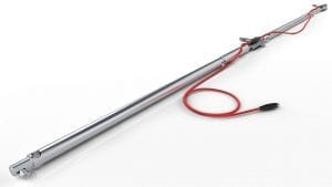
The anatomy of an IPI system
Each IPI contains a triaxial MEMS accelerometer sensors housed inside a 28.6 mm (1.125 in.) diameter, watertight, stainless-steel enclosure. The sensor body is rigidly connected to a 25.4 mm (1.0 in.) diameter bay rod which establishes the length of the IPI. Multiple IPIs are assembled with pivots allowing for sensing of displacement over discreet, configurable intervals. Wheel assemblies centralize the pivot point and establish the azimuth of each IPI. They are available in sizes to fit 70 mm (2.75 in.) or 85 mm (3.34 in.) O.D. inclinometer casings.
Deployable in boreholes as deep as 100 metres, RST’s MEMS Digital In-Place Inclinometer (IPI) System is designed to reliably measure lateral movement in and around dams, embankments, landfills, landslides, piles, piers, retaining walls, and abutments, particularly when continuous remote monitoring is required. Features include:
- Wet-mate submersible connector
- Precision locking and tool-free assembly
- Industry-leading system weight for ease of transport
- Both biaxial and uniaxial applicability in one model
Reference:
Steiner, W., International standards for geotechnical monitoring under ISO, Canadian Geotechnique, Vol. 3 No. 1 Spring 2022
ISO 18674-3:2017 Geotechnical investigation and testing — Geotechnical monitoring by field instrumentation. Part 3: Measurements across a line – inclinometers.
Speak with an expert about the MEMS Digital In-Place Inclinometer System’s specifications today